Distance and heading control
Drive and turn routines use the platform's incremental distance and angle feedback. Movement can exit when a stop request, manual takeover, bump, or cliff condition is detected.
CPRE 288 · Embedded Systems · Spring 2026
Making a robot decide when to move, when to investigate, and when to hand control back.
A naval mine-search simulation built on a ground-based CyBot with a TI TM4C123GH6PM microcontroller. The robot combines a scanning sensor head, differential-drive movement, and manual and autonomous control to explore a course containing obstacles and simulated mine targets.
My contribution
I developed the main program, movement routines, and behavior logic for both autonomous operation and manual driving. My work also covered the timer, scan, ultrasonic ping, and servo modules, connecting low-level sensing and timing to decisions about where and when the robot should move.
Drive and turn routines use the platform's incremental distance and angle feedback. Movement can exit when a stop request, manual takeover, bump, or cliff condition is detected.
The autonomous loop chooses between investigating targets, rescanning uncertain detections, facing a gap, and searching in another direction. Recovery behavior handles obstacles and course boundaries.
I worked on the scan functions that coordinate sensor-head positioning and range acquisition, along with the ping driver that triggers the ultrasonic sensor and captures its echo pulse with timer interrupts.
My work included timer integration for waits and elapsed-time checks, and servo positioning through timer-generated PWM. Calibrated endpoint counts map a requested angle to the sensor head's control signal.
The complete system is a team effort, combining my main-control, timer, scan, ping, and servo work with the ADC and communication modules, a Python operator interface, and course-provided platform utilities.
System architecture
A PC interface sends operator commands over a socket connection, while the embedded firmware receives control bytes through UART. The main loop combines those commands with scan results and feedback from the mobile base.
Mode selection, drive commands, scan requests, and telemetry display.
UART command flags, movement routines, and behavior decisions in C.
Wheel control, servo-mounted IR and ultrasonic ranging, bump and cliff feedback.
Feedback closes the loop: distance and angle increments update a relative position estimate, and the firmware reports object angles, ranges, widths, and operating status. This is a local navigation strategy using odometry and repeated scans, rather than a global route planner.
Control & behavior
Manual mode
The operator drives with W/A/S/D and requests a scan while stationary. The drive routine stops issuing movement when a command has not been refreshed for 250 ms. This is a command-age threshold in the firmware, not a measured end-to-end stopping time.
When a bump or boundary is detected, forward motion is blocked while reverse and turning commands remain available for recovery. A scan clears the active movement command before collecting data.
Autonomous mode
Autonomous mode is selected separately from its start command. Once started, the loop checks for hazards, scans for targets and gaps, and chooses its next action.
Confirmed targets trigger a stop, an angle report, sensor-head pointing, an audible indication, and a pause for simulated removal. A rescan checks whether targets remain before the counter advances.
| Condition | Robot response |
|---|---|
| Bump during autonomous operation | Stop, reverse, and attempt a turn and detour based on the bumper side. |
| Boundary or hole indication | Stop, back away, and choose a turn using the left/right cliff sensor readings. |
| Confirmed simulated mine | Report and point at the target, pause for removal, then rescan. |
| Detection in only one sweep | Report uncertainty, back up slightly, and scan again. |
| Traversable gap | Turn toward its midpoint and attempt a checked forward step. |
| No target or usable gap | Turn left to search from a different heading. |
| Stop or manual takeover request | Exit checked movement, scan, or waiting routines when their interruption checks run. |
Sensing & decisions
The scanning pipeline uses infrared range estimates to locate object edges across the forward field of view. After a segment is found, the servo points at its midpoint and an ultrasonic measurement provides range for the width estimate.
w = 2d × tan(Δθ / 2)Here, d is the midpoint range and Δθ is the object's angular span.
The final working firmware sweeps from 0° to 180° in 1° steps. It treats widths from 2–7 cm as potential mine targets, subject to visibility and filtering checks. Partially visible edge objects remain obstacles, and nearby narrow segments are checked for the possibility that they belong to one wider object.
The ping driver uses PB3 and Timer 3B edge-capture interrupts to record the echo pulse. Pulse duration is converted to a distance estimate, with a 20 ms wait limit that returns an invalid reading if the echo does not complete.
The servo module uses Timer 1B PWM on PB5. It clamps requested angles to 180° and maps them between calibrated endpoint counts. Timer 5 provides the elapsed-time utility used by the program, while the scanning functions coordinate servo movement, IR readings, and midpoint ultrasonic measurements.
Two sweeps are compared using angle and range tolerances. Matching candidates are averaged into a confirmed detection. A candidate appearing in only one sweep prompts another look instead of immediately advancing the task.
The scan also tracks clear angular intervals and estimates gap width. When both sweeps indicate a usable gap, the controller can align to its midpoint. Forward motion remains subject to bump and cliff checks.
These thresholds are implementation settings. They do not establish measured detection accuracy, range accuracy, or a guaranteed collision-free path.
Engineering choices
Longer operations contain explicit checks for operator requests. Autonomous scans permit manual takeover, and the simulated-removal wait checks for stop and mode changes. UART status messages are deferred to the main loop through a pending-status byte.
A hazard response cannot always reuse the same checks as forward travel: a bumper may remain pressed while reversing away. The movement helper accepts separate bump and cliff checks, allowing recovery routines to choose which conditions to monitor. Those exceptions make recovery possible, but they also need careful physical testing.
Drive distance accumulates the base's feedback instead of relying only on a timed motor command. Turns accumulate reported angle and apply separate left/right offsets. Relative position is estimated from distance and heading, so drift remains a limitation without an external position reference.
Repeating a scan and checking ambiguous detections adds delay, but gives the controller more evidence before acting. The implementation exposes this decision process through serial messages so the operator can see why the robot rescans or changes direction.
Recorded evidence
The saved sensor log contains manual scan requests, object measurements, target reports, and scan-completion messages. This excerpt captures one reported target:
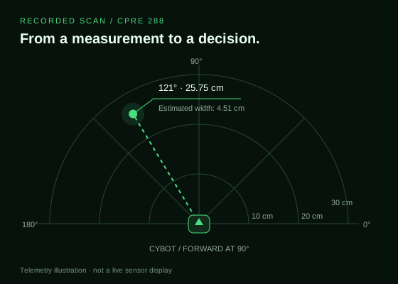
Object angle 116-126 mid 121 dist 25.75 width 4.51
…
Mine 1 angle: 121 dist: 25.75 width: 4.51
SCAN END
The target report places the object at 121° and approximately 25.75 cm, with an estimated width of 4.51 cm. A later scan in the same log reports approximately 25.76 cm and 4.51 cm for a target at the same angle. These are the robot's estimates from a recorded session; the log does not provide ground-truth measurements for an accuracy calculation.
The firmware includes both operating modes and a completion condition based on a six-target counter. The available log documents manual scanning; it does not establish a full autonomous mission result or a measured success rate.
Project focus
The central engineering work was coordinating these pieces into understandable behavior: know why movement started, check what should interrupt it, and choose a recovery action when the environment changes.