Personal · Audio Arduino Club
Altoids
Headphone Amp.
A stereo amplifier small enough for a mint tin.
A compact, battery-powered headphone amplifier I built in Audio Arduino Club under Dr. Gary Tuttle.
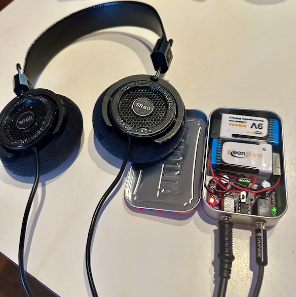
Situation
Start with a compact audio circuit
Audio Arduino Club offered a practical way to connect circuit theory with a physical build. The Altoids design uses two non-inverting amplifier channels to boost a wired headphone signal.
Task
Build the club’s headphone amplifier
My task was to assemble the provided circuit and work through its compact packaging under Dr. Gary Tuttle’s guidance. The focus was component identification, soldering, and understanding the signal and power paths.
Action
Work from the small parts outward
The build progresses from the input and feedback components to the socket, power switch, capacitors, and audio jacks. Two 9 V batteries supply the TL082 circuit. The enclosure design places the connectors through the tin and insulates the board from its metal base.
Circuit design and component choices
A TL082 dual op-amp provides one non-inverting stage for each stereo channel. The 15 kΩ and 1 kΩ feedback resistors set a nominal voltage gain of 1 + 15/1 = 16. The two batteries create positive and negative supply rails around a common ground, allowing the audio signal to swing on either side of zero.
| Component / setting | Value and purpose |
|---|---|
| TL082 + feedback network | Dual op-amp; two 15 kΩ and two 1 kΩ resistors set the channel gains. |
| Input components | Two 100 kΩ resistors and two 100 nF capacitors form the input networks. |
| Supply bypassing | Two 100 µF electrolytic capacitors help stabilize the battery supply rails. |
| Power & indication | Two 9 V batteries, a double-pole switch, and red/green LEDs with 1 kΩ current-limiting resistors. |
| Audio connections | Separate stereo input and output jacks; volume is adjusted at the source. |
Build process
- Populate the small components
Start with the input and feedback resistors, then the small capacitors. The board’s ground plane draws heat away from solder joints, making consistent heating especially important at ground connections.
- Assemble and check the power path
Add the socket, switch, battery terminal, bypass capacitors, and jacks. The guide calls for checking the supply rails and switch operation before installing the semiconductors; capacitor polarity and op-amp orientation are key checks.
- Fit the enclosure
The guide places two ¼-inch connector holes 24 mm apart in the tin. An insulating layer keeps the PCB underside away from the metal enclosure, while the connector nuts secure the board. The batteries share the remaining space.
The gain above is calculated from the design values. It is not a measured result from my individual build.
Result
Connect electronics with packaging
I completed the Altoids amplifier project as a hands-on club build. It brought together stereo op-amp circuitry, through-hole assembly, and the mechanical constraints of a small enclosure.
Design & build process
From components to a complete board.
Reference photographs extracted from Altoids Amp — Build, G. Tuttle, 2023. These show the club’s reference builds.
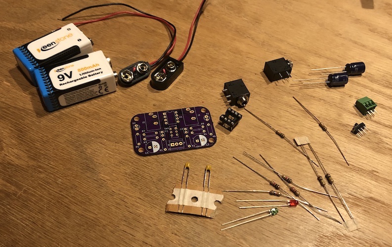
01 / Parts & layout
The parts set pairs a small PCB with through-hole components and audio connectors.
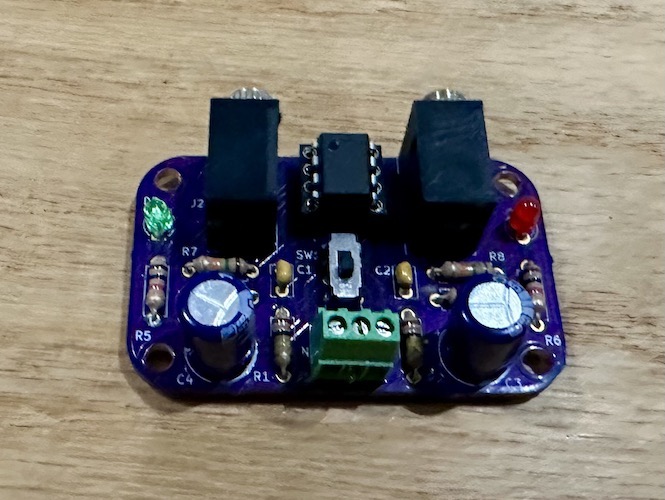
02 / Board assembly
The assembled board brings together the two channels, power switch, and battery connections.
03 / Enclosure & connections
The guide’s finished example fits the board and two batteries inside an insulated mint tin.
Circuit design and build guidance: Dr. Gary Tuttle / Audio Arduino Club. My role: building and learning from the club design.